


Class 10 th Electricity part 1st
INTRODUCTION
Electricity is probably the eighth wonder of the modern civilized world. Its discovery and usefulness have revolutionized the homes and industries of the civilized world. Life today totally depends on it. look at effects on our lives of a power failure that lasts only a few hours. Think of all the devices that are based on it; lights, radio, television, engines to drive the wheels of industry. The list is endless. Electricity is one of the forms of energy and can be produced from other types of energy, such as energy from a chemical reaction or mechanical rotation of a dynamo. Its great advantages over all other types of energy are your:
(i) cleanliness (no smoke or odour),
(ii) flexibility (with respect to voltage),
(iii) efficiency and
(iv) Easier transmission over long distances (requires only two wires, no more than an inch of diameter compared to large oil and gas pipelines or large container for coals). The use of electricity has grown rapidly with requires doubling every seven to ten years. Basic concepts of electricity, that is, its nature, the process by which it flows in an electrical circuit and factors that regulate its flow in the circuit, its heating effect and its applications,
DISCOVERY OF ELECTRICITY
Although it is impossible to say when the electricity was first discovered, records show that as early as 600 BC, the attractive property of amber (a transparent fossil resin) was known. Thales of Miletus (640-546 BC), one
of the seven wise men of ancient Greece, is said to have observed the attraction of amber, when previously rubbed, for pieces of straw. In fact, the word electricity has been derived from the Greek word electron, meaning amber. Little progress was made in this field until the 16th century. century after Christ. Then Sir William Gilbert (1540-1603) found that substances other than amber could also be electrified, for example, glass rod when rubbed with silk. Charles Francois Du Fay (1698 - 1739) of France found that there was There are two types of electricity, Benjamin Franklin (1706–1790) gave the name of positive electricity to the charge on the glass rod rubbed with silk and negative electricity to charge on ebonite rod rubbed with skin.
Electric charge: Electric charge is one of the basic properties of matter with which it interacts. With Other related effects . It can also be defined as the property due to which a
The substance attracts other small substances. From The structure of the atom has been revealed. That a body gets +ively charged if it looses election and -ively charged if looses gains electron . The SI unit of charge is Columb , denoted by "C".
PROPERTIES OF ELECTRIC CHARGE
1. Unlike (opposite) charges attract each other and like (similar) charges repel each other.
2. The force (F) between two charges varies directly as the product of two charges (91 and 92) and inversely as the square of the distance (r) between them, i.e.,
F ∝ = q1q2/r2 or k=q1q2/r2
where k is a constant of proportionality.
3. Electric charge is conserved, i.e., it can neither be created nor destroyed.
4. Electric charge is additive, i.e., total charge is the algebraic sum of the individual charges.
5. Electric charge is quantised and the quantum of charge (i.e., the minimum charge which is capable of free existence) is equal to that on an electron. Any other charged body will have a charge, Q where
Q=ne
where n = +- 1,+- 2,and
e = charge on an electron = 1.6 x 10⁻¹⁹ coulomb.
Unit charge: A charge is said to be one coulomb if it exerts a force of 9 x 10° N on an equal charge placed at a distance of Im from it in air. An electron is negatively charged particle of 1.609 x 10⁻¹⁹C of charge.
CONDUCTORS AND INSULATORS
Substances can broadly be classified into two categories depending upon whether they conduct electricity or do not conduct electricity
1. Conductors. Substances through which charge scan easily pass are known as conductors, Metals, acquis solutions of salts and ionized gases are all conductors, In case of solid conductors, there are free electrons(also called the conduction electrons) which account for their ability to conduct electricity through them,
2. Insulators. Substances through which charges cannot pass are called insulators. Glass, porcelain, pure water and all gases are insulators. Insulators are also called dielectrics. In insulators, the electrons are strongly bound to their atoms and cannot get themselves freed. Thus, free electrons are absent in insulators. Insulators can easily be charged by friction. This is due to the reason that when an electric charge is given to an insulator, it is unable to move freely and remains localised. But this does not mean that conductors can not be charged by friction. The only difference in their case is that the charge is not localised and flows to earth if it finds a conducting path (like our body). A metal rod can be charged by rubbing it with fur or silk if it is held in a handle of glass or amber (i.e., an insulator).Electricity is broadly classified as:
(a) Electrostatics or Static Electricity. This branch of electricity, the earliest discovered, deals with the study of charges (i.e., electrons) at rest (i.e., static).
(b) Current Electricity. When charges are in motion, they constitute what is called an electric current or simply the current in the day-to-day language. Current electricity deals with the fundamental concepts and the physical effects of electric current and this is going to be the subject of our discussion in this chapter.
Electric potential. It is defined as the amount of work done in moving a unit +ive charge from infinity to present location. It is denoted by 'V' and is measured in volts. Potential at a point is said to be one volt if one joule of work is done in moving a unit +ive charge from infinity to that
Potential difference: The potential difference between two points in an electric circuit is defined as the amount of work done in moving a unit +ive charge from one point to the other point
Potential difference = work done/Quantity of charge moved
if W is the amount of work done in moving a charge of Q coulombs from one point to another, then potential difference V between two points is given by V = W/Q
Unit of electric potential difference:
The S.I unit of potential difference is volt,
if w = 1J, Q = 1C
V = 1J /iC= 1JC-' = 1V
i.e. potential difference between two points is said to be one volt if one joule of work is done
In moving a charge of IC from one point to the another. The potential difference is measured by a device called the voltmeter. It is always connected in parallels to a conductor.
THE ELECTRIC CURRENT
We know that a Water current means flowing of water and an air current is motion of air. Similarly, when an electric current flows through a conductor, it is said to constitute an electric current. An electre current is defined as the ordered motion of electric charges .Quantitively, electric current is defined as the raw flow of electric charge, le, electric current in the quantity of charge flowing per unit time,
If charge (Q) flows through a conductor in a time (t), then current(I) in flowing through the conductor
I =Q/t
Q=I/t
Unit of Corrent. The SI unit of current in called an ampere (A) in honour of french scientist, Andres Marie Ampere (1775-1836).
I ampere=1coulomb/1second
1A=1C/s
Thus, current flowing through a conductor is said to be one ampere if one coulomb of charge flows through it in one second
Small quantities of current are measured in milliampere (mA) and in microampere (úA) where
1 mA-10-³A and 1ù A 10-6 A
Definition of coulomb
the definition of a coulomb, which is a unit of charge, is derived from ampere because ampere is one of the seven base units of SI
One coulomb of charge is that quantity of charge which flows through a circuit when one ampere of current flows through it in second
Direction of Current. The conventional
The Convention direction of an electric current is considered to be the Current one in which the positive charges move orderly, Since in metallic conductors, the current is carried by the free electrons, the conventional current is in a direction
opposite to the electron flow, i.e., electron current as shown in Fig.
+ ----------------->+ ----------->+ conventional current

Types of electric current
1)Direct current (D.C): An electric current is said to be direct current if its magnitude and direction do not change with time (steady D.C)
(OR)
An electric current is said to be direct current if its magnitude changes with time and polarity remains same (variable D.C)
steady D.C
variable DC
variable D.C
2)Alternating current (A.C: An electric current is said to be alternating current if its magnitude changes with time and direction reverses periodically. It fallows since wave and alters time.
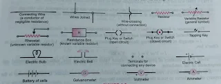
Electric circuit and its components:
A continuous conducting path consisting of wires and other resistances (electric bulb, fan. press etc) and a switch, between the two terminals of a cell or a battery along which electric current flows is called as an electric circuit. A drawing showing the way the electric devices are connected in a circuit is a called a circuit diagram or schematic diagram. In these diagrams certain symbols are used to represent different devices as shown
in figure. Of electronic circuit
Ohms Law(v.v.imp)
George Siemen Ohm derived a relationship between the potential difference applied comes a conductor and the current flowing through it and this relationship is simply called Ohm's law which states that the current flowing through a conductor is directly proportional to the potential difference applied across its ends provided the physical conditions like temperature pressure, mechanical strain) are kept unchanged. Mathematically, if I is an electric current flowing through a conductor and ,V, be the potential difference applied across its ends then according to Ohm's law,
V ∝ 1 (at T = constant)
V=IR
Where 'R' is the constant of proportionality called as the resistance of the conductor whose value depends upon length, cross sectional area and the nature of the material of the conductor.
The above equation can also be written as V/I=R
Thus, Ohm's law can also be stated as "The ratio of the potential difference applied across the ends of a conductor to the current flowing through it is constant, provided the physical conditions of the conductor do not change
Experimental Verification of Ohm's Law:
To verify Ohm's law, take a resistor R, connect voltmeter across it. Connect an ammeter, battery, key and rheostat to it as shown in Fig. 3.8. Put in the key K. Read the value of potential difference across resistor R with the help of voltmeter and the current flowing through resistor with the help of ammeter. Note the readings. Vary the current in the circuit by sliding rheostat and go on noting reading in voltmeter and ammeter. Plot a graph between V and I on graph paper. It will come out to be straight line as shown in
Fig.

Definition of Resistance
The resistance of a conductor is the ratio of the potential difference across its ends to the strength of the current flowing through it. In fact, resistance of a conductor means the obstruction to the flow of electrons through it. While representing it diagrammatically, this obstruction is represented by hills as (www-). In case of a connecting wire made of copper which is a very good conductor, the obstruction offered to the flow of electrons is practically zero and as such a connecting wire is represented by a straight line -) without hills. A material is a good conductor if it has low resistance. On the other hand, a material which has a high resistance is called a bad conductor or an insulator. But it should be remembered that even a very good conductor has some resistance, though negligible.
Unit of Resistance. The SI unit is the practical unit of resistance and is called ohm. It is represented by the symbol, S2.
The resistance of a conductor is said to be one ohm if a current of one ampere flows through it when a potential difference of one volt is applied across its ends.
R=V/I, 1Ohm=1Volt/1amper....ie
1ohm=1v/1A
Difference between Resistor and Resistance
A resistor is an object of some conducting material having resistance of a desired value. Thus, a resistor is an object and resistance is its electrical property due to which it opposes electric current. Whenever we say that we have a resistance of 5 ohm, it means that there is a resistor which offers a resistance of 5 ohm
Resistivity of a material :- is defined as the resistance offered by a cube of the material of side one metre when the current flows perpendicular to the opposite faces of the cube,
or
Resistivity of a material is also defined as the resistance offered by a cylindrical conductor of the material of cross-sectional area one metre and length one metre when the current flows. perpendicular to the opposite ends of the cylinder.
CLASSIFICATION OF MATERIALS ON THE BASIS OF RESISTIVITY
On the basis of their resistivity and its dependence on temperature, materials are divided into four Categories
1. Conductors (Metals and Alloys). Metals like copper, aluminium, silver, platinum etc. have a large number of free electrons and as such possess small resistivity (in the range of 10-8 ohm m to 10 ohm m) which increases with temperature (i.e., a is positive). In case of alloys such as nichrome, manganoan, constantan (also called eureka), resistivity is more than that of the constituent metals. But it increases slowly with temperature than in case of metals. In other words, in case of alloys though a. is positive but its value is extremely small, i.e., p is nearly independent of temperature.
2. Semiconductors. These possess a few free electrons and as such possess greater resistivity in the range of 10-9 to 102 ohm m) as compared to conductors. The resistivity of semiconductors decreases with temperature (i.e., a is the negative). Silicon and germanium are the common examples of semiconductors.
3. Insulators. These have practically no free electrons and as such have a very high resistivity in the range of 1010 ohm m to 1017 ohm m) which decreases with rise in temperature (i.e., a is negative). Mica, rubber, glass, china clay and fused quartz belong to this category.
4. Superconductors. These are materials (metals and compounds) whose resistivity becomes zero below a certain temperature, called critical temperature. The resistivities (in ohm m) of different materials at 20°C and their mean temperature coefficients of resistivity in °C-'are given below. Fig
 |
Resistivities and temperature coefficient of conductors, semiconductors and insulators |
COMBINATION OF RESISTORS (or RESISTANCES) IN SERIES AND PARALLEL
Resistances can be joined either in series or in parallel Series combination is used when the resistance in the circuit is Quite often, we have to connect more than one resistors in a circuit for practical purposes. The resistors to be increased or current is to be decreased. Parallel combination, on the other hand, is used when the resistance in the circuit is to be decreased or current is to be increased. We shall discuss each one of these combinations in detail.
(a) Resistors (or Resistances) in Series.
A number of resistors are said to be connected in series if these are joined end to end and the same (i.e., total) current flows through each one of them when a potential difference is applied across the combination. As shown in
Fig.

(R1, R2, R3 = three resistors connected in series,
V = potential difference across A and B.
V1, V2, V3 = potential differences across R1, R2 and R3 respectively,
1 = current flowing through the combination.
It is clear that
V = V1 + V2 + V3......1st eq
According to Ohm's law,
V = IR , V2 = IR, and V3 = IR3.......... (2ndeq)
Let Rs ,be the equivalent or resultant resistance of the combination. Obviously, when such a resistance is connected between the points A and B and a potential difference, V is applied between these point allows a current, 1 to flow through it,
V=IRs.................... (3rd eq)
From eqns. (1) and (2) and (3),
IR, = IR, + IR2 + IR;
Rs = R 1+R2+R3
Hence, when a number of resistances are connected in series, the equivalent, i.e. resultant resistance is equal to the sum of the individual resistances and is greater than any individual resistance.
Resistors (or Resistances) in Parallel.
A number of resistors are said to be connected in parallel if one end of each resistor is connected to one point and the other end is connected to another point so that the potential difference across each resistor is the same and is equal to the applied potential difference between the two points. As shown in Fig.

Ry, Ry, Rz = three resistors connected in parallel,
V = potential difference across the points A and B,
I = total current flowing between the points A and B,
I¹, I², I³ = currents flowing through R¹, R² and R³ respectively.
It is clear that I = 1¹+1²+1³........................(.i)
Since potential difference across R¹ R² and R³ is the same, i.e., V. according to Ohm's law,
I¹=V/R¹, I²=V/R², I³=V/R³.......................( ii )
Let Rp be the equivalent resistance. Obviously, when such a resistance is connected between A and B, [Fig.(b)) and a potential difference V is applied across its ends, it allows a current I to flow through it.
Clearly, I=V/Rp................................(iii )
From equations. (1), (2) and (3)
V/Rp= V/R¹+V/R²+V/R³ or
1/Rp= 1/R¹+1/R²+1/R³
Hence, when a number of resistances are connected in parallel, the reciprocal of the equivalent, ie., resultant resistance is equal to the sum of the reciprocals of the individual resistances and is smaller than any individual resistance.
Heating effect by an electric current
Whenever a current is passed through a conductor, it becomes hot after sometime. This means that electric energy is being converted into heat energy. Electric bulb, electric furnace, electric iron, electric heater etc, are some of the appliances which are based on this effect, called the heating effect of current or the Joule heating.
It is to be noted that heating effect is not always desirable. For example, in case of an electric motor, an electric generator and a transformer, heating due to current involves dissipation of electric energy, i.e., wastage of electric energy and also damages these equipment's.
Let us now try to understand the mechanism of heat production by an electric current. We know have free electrons. When a potential difference is applied between the ends of a conductor, these electrons begin to move from a lower potential (negative terminal) to a higher potential (positive terminal). The movement of these electrons is not continuous because they experience resistance due to their collisions. with other electrons and also with the ions in the conductor . As a result of this, work is done to overcome this resistance (obstruction to the flow of electrons). It is this work done that becomes heat. In fact, when the electrons collide with the ions, the ions begin to vibrate rapidly, and that fast. vibration of ions appears in the form of heat. It is note to worthy that
1. The greater the number of electrons flowing per second (i.e. current), the greater the number of collisions and the greater is the heat produced.
2. The heat produced also depends on the resistance of the conductor which determines the difficulty with which the electrons flow,
3. If the current passes for a longer time, more collisions occur between the electrons and the ions and therefore more heat is produced. Therefore, the heat produced by a current flowing through a conductor depends on
(a) strength of the current flowing through the conductor,
(b)the resistance of the conductor,
(C) the time during which the current flows.
In 1841, James Prescott Joule (1818 - 1889) experimentally studied the heating effect of an electric heater. current and concluded that the amount of heat produced (H) when a current, 1 flows through a resistance conductor, R for a time, t is given by
H ∝ I²Rt
This relationship is called Joule's Law of heating.
............
Blog continue
for 2nd part click on the below link
https://jkgovtschoolnotes.blogspot.com/2022/01/class-10-electricity-2nd-blog.html


1 Comments
Vrey good
ReplyDelete